Suspension K&C Rig
This was my rookie project on Penn Electric Racing's suspension team. K&C stands for Kinematics and Compliance, and the goal was to actually measure how our suspension behaves in the real world instead of just trusting the design intent from CAD and simulation. Suspension geometry gets designed around tire sensitivity to hit target camber and toe ranges, but design intent doesn't guarantee real-world behavior, so the whole point of this rig was validation.
I broke the measurements into three buckets: kinematics, compliance, and rates.
Kinematics is how the wheel's position and orientation change with bump, droop, and steer. The things I cared about were camber vs. bump, toe vs. bump, camber and toe vs. steer, and motion ratio (which is the ratio of shock displacement to wheel vertical displacement). These all matter because cornering puts one wheel in bump and the other in droop, and camber and toe define the contact patch and slip angle, which is where all the grip comes from.
Compliance is the deflection in parts that we assume are infinitely stiff but actually flex a little under load. It tells us how wheel geometry changes with respect to lateral force (Fy) and turning moment (Mz). Testing this helps prevent system failure, validate FEA, adhere to FSAE rules, and pick the right camber setup.
Rates are the spring rates of the system: ride rate, tire rate, and ARB rate. These set how the car responds to load and how front-to-rear balance is tuned.
Measuring Rates
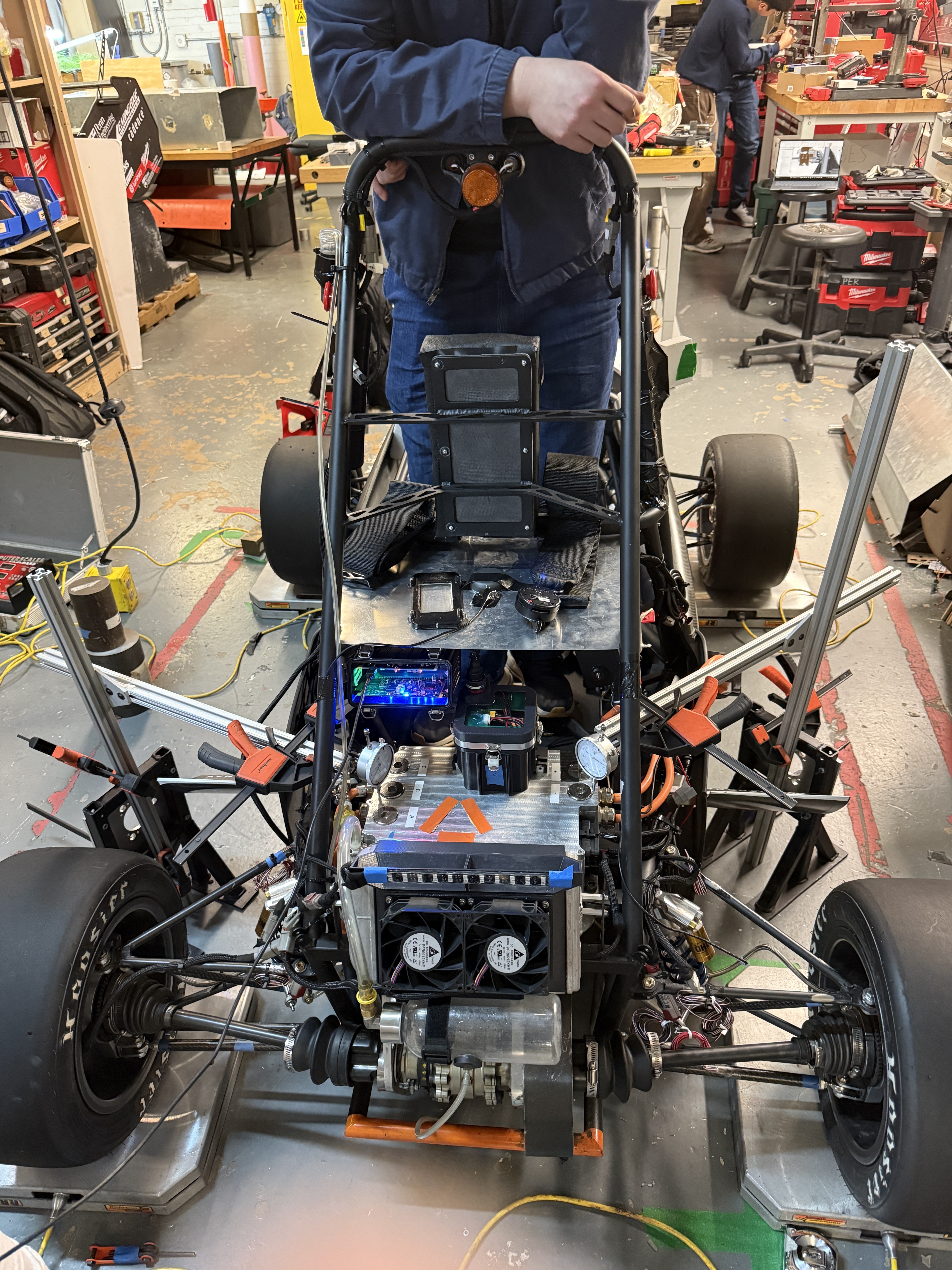
For ride rate, I put scales at each corner, mounted dial indicators on the front and rear, had someone stand on the chassis, and measured deflection at the chassis tubes. The early data was a little sketchy (the brakes weren't on, which let the car move more than it should), but the trend was clear and I planned to redo it with the brakes locked. I got values like FL: 90.62, FR: 93.86, RL: 175.12, RR: 132.47 lbs/in.
For tire rate, the first setup (a plate on top of a single tire with weights) failed because the tire wedged and the whole thing was unstable. The second setup lined up two tires horizontally with a plate and weights on top, treating each tire as two springs in series and two of those in parallel. That gave around 546 lbs/in per tire at 20 psi, which is on the soft side. The takeaway was that I need a proper rig constrained by linear slides to get clean, repeatable numbers.
Measuring Kinematics
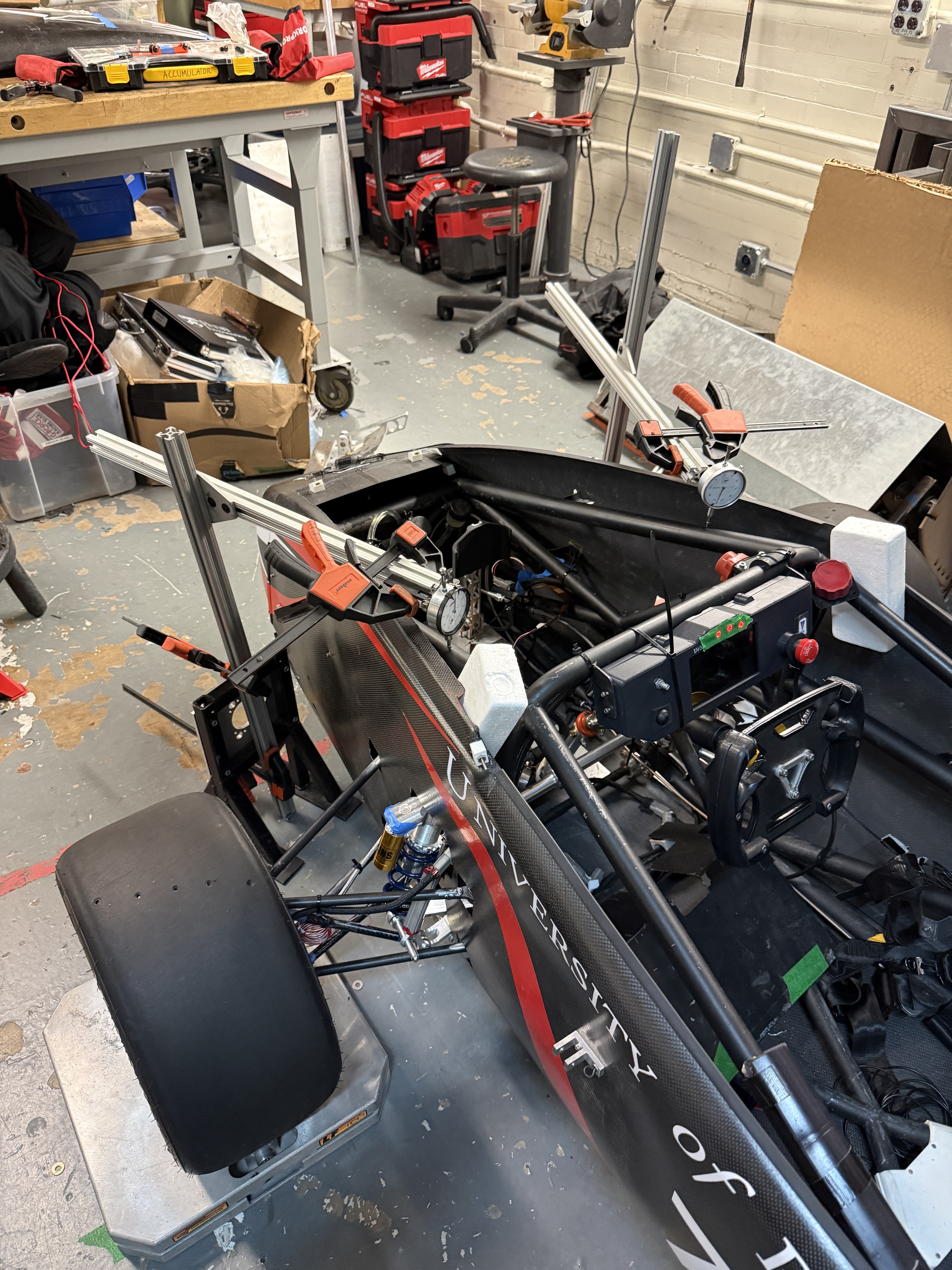
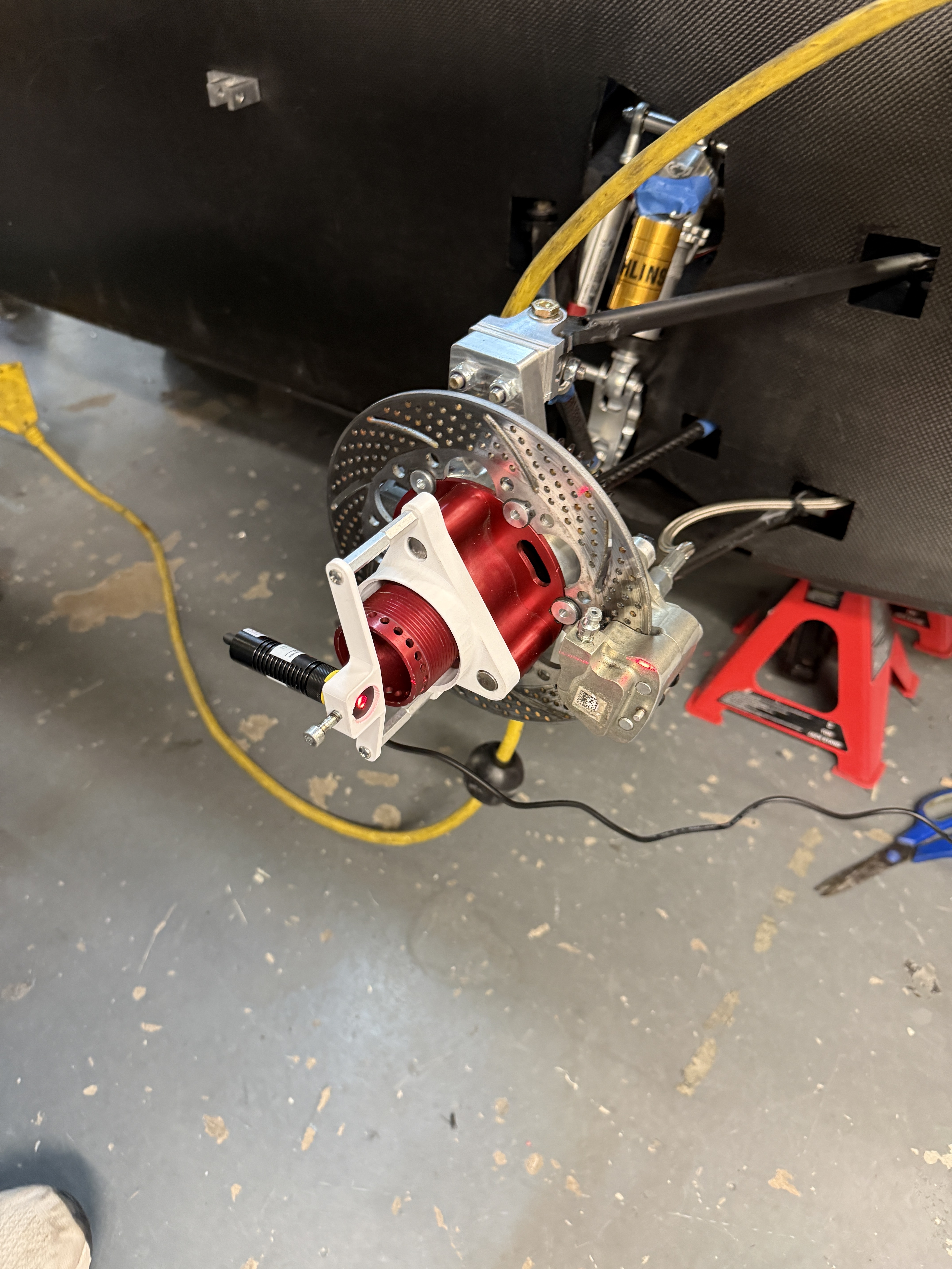
The original plan used lasers mounted to the wheel nut with fake shocks to push the wheel through bump and droop, reading toe and camber off how the laser dots moved (toe = arctan(Δx/distance), camber = arctan(Δy/x)). The newer setup put the car on jacks and used a scissor lift to move the wheel, with angle sensors reading camber directly. The angle sensor resolves to about 0.1°, and I measured roughly 5.2° of camber change with steer and 1.3° with bump.
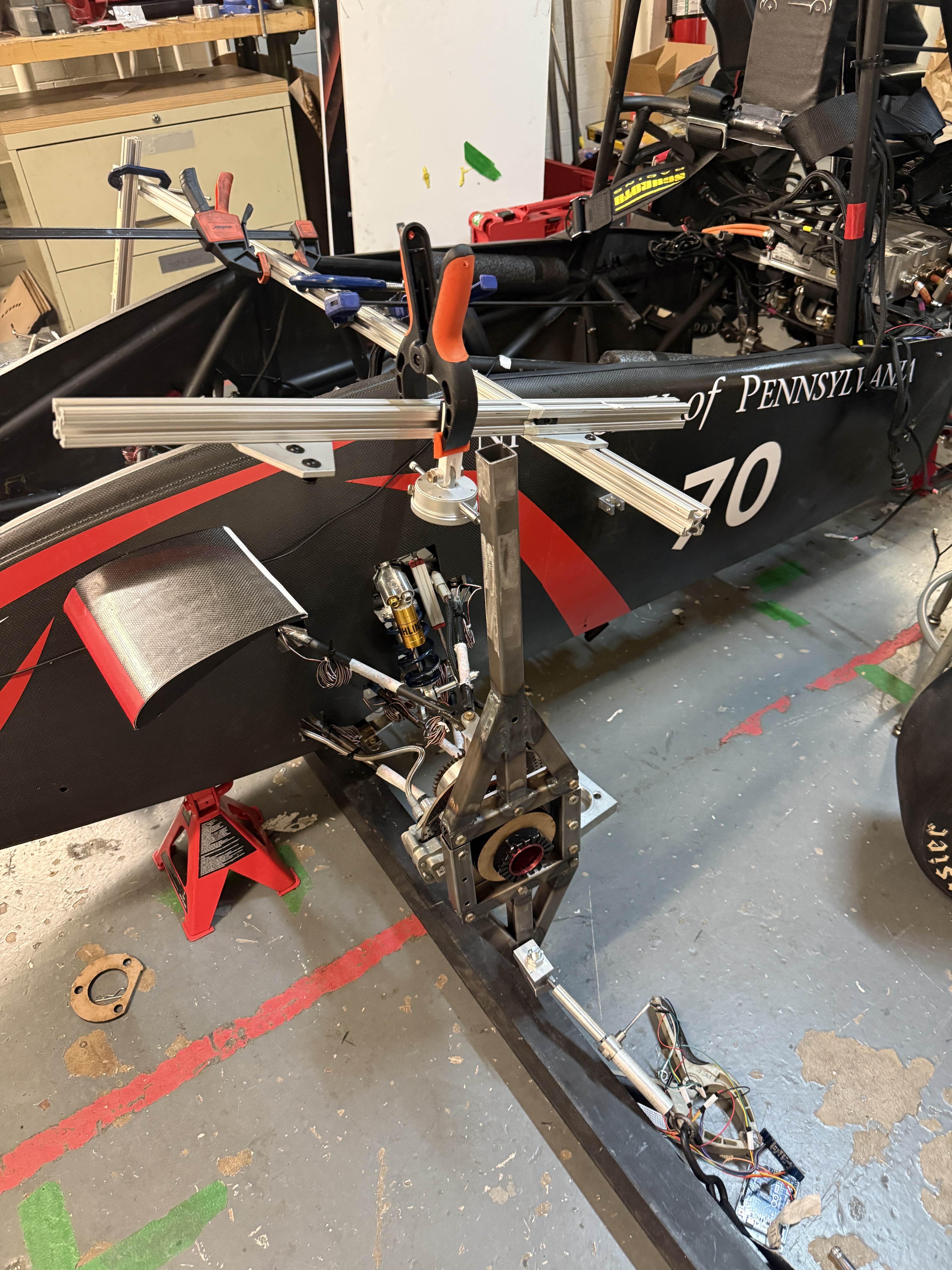
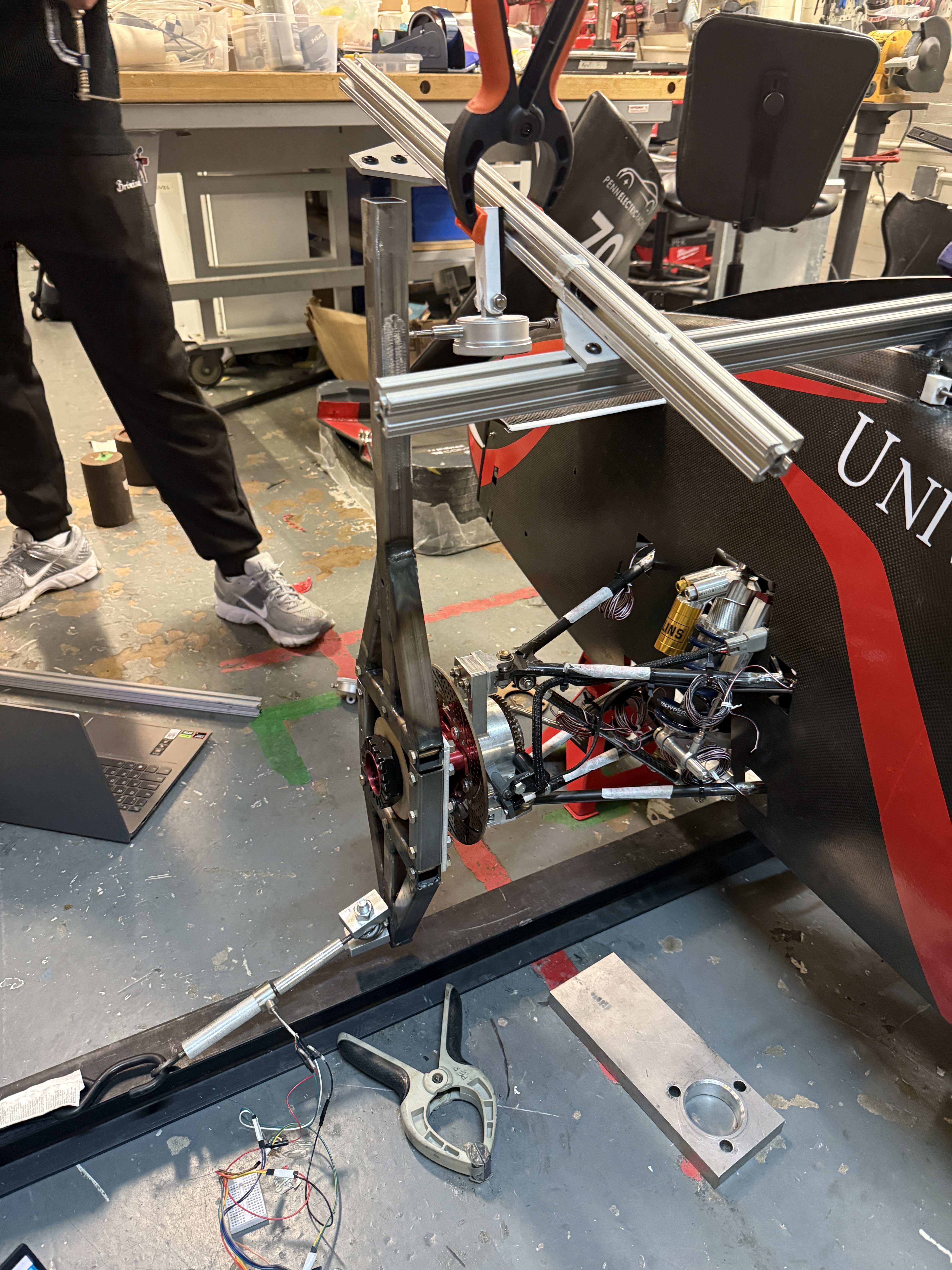
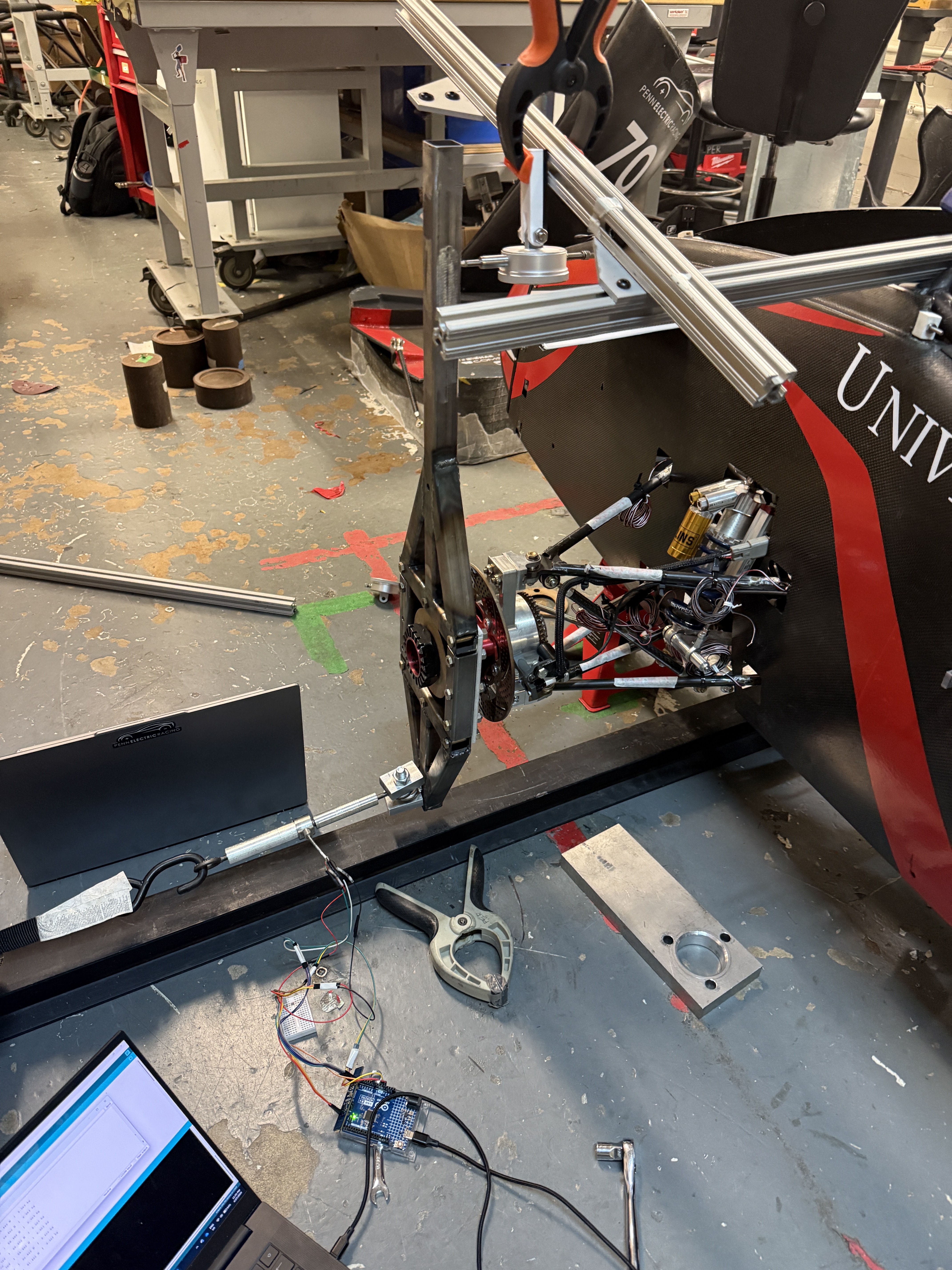
Measuring Compliance
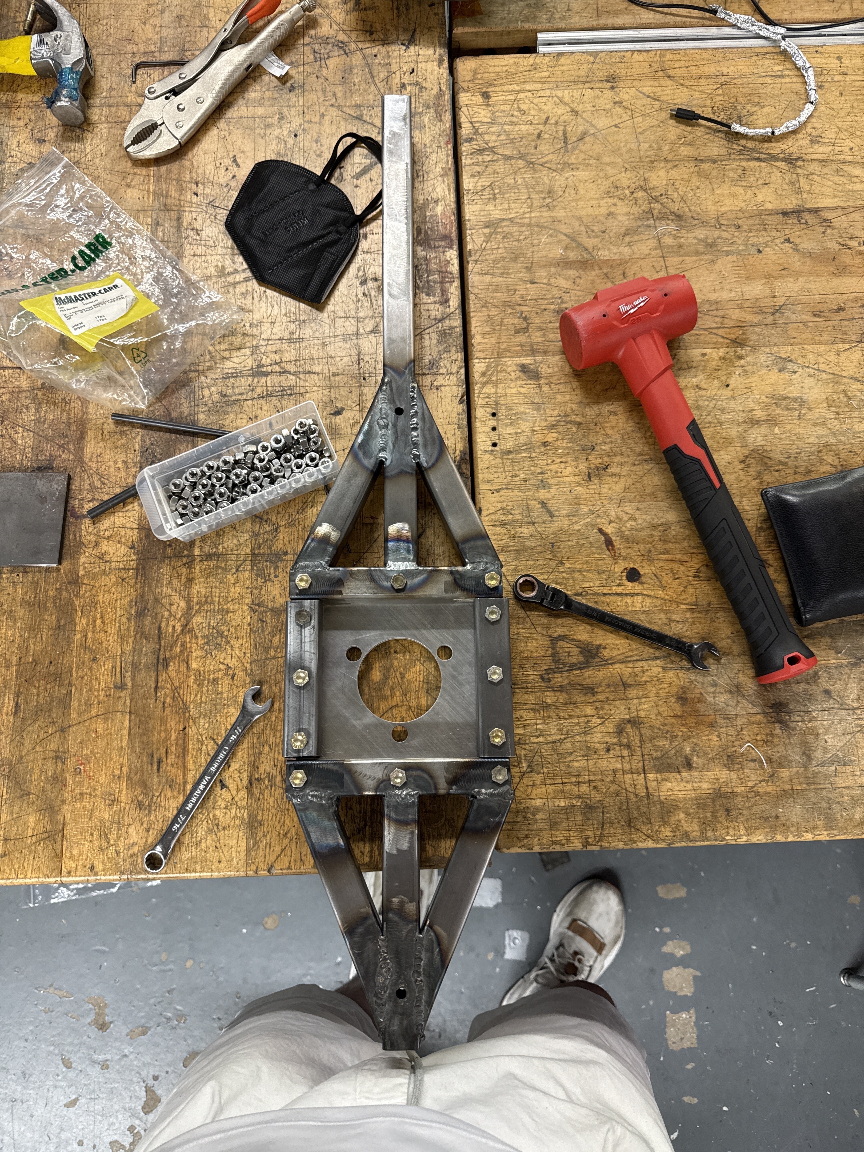
This was the most involved part. I modified our existing torsion rig so it could apply force at the contact patch, using an I-beam to keep the reaction forces internal and a dyno load cell to read the load. The car sits on jacks with the steering locked. The targets were toe and camber as functions of Mz and Fy, which combine into compliance coefficients. I ran FEA on the rig, the anchor, and a revised version to make sure nothing yielded under the max lateral load of 1650 N, iterating from V1 (which exceeded yield) to V2 (which didn't).
What I Took Away
This project taught me a ton about the gap between a clean CAD model and a messy real-world measurement. Half the work was just getting setups stable and repeatable enough to trust the numbers. The next steps are building a dedicated tire-rate rig on linear slides and rerunning the ride rate test with the brakes locked.